Automated assembly of components for new eco-friendly generations of engines
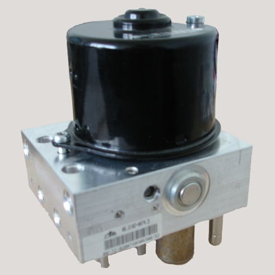
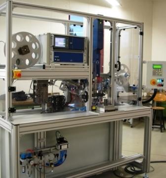
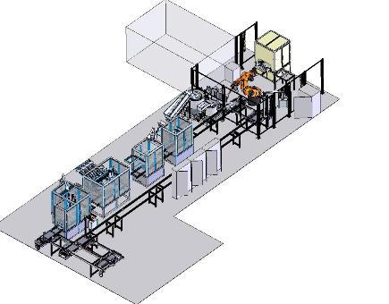 For the production of a motor assembly, the FLG Automation AG has developed and realized a complete assembly line . On it, the control boxes for new engine series of environmentally friendly vehicles of the middle class are fully assembled and tested.
In the foreground in the interpretation stood beside the high quality demand s of the car producing company, a full traceability of manufactured components and high process reliability. All through the resulting assembly and tester results associated with the individual control unit features a RFID chip in the workpiece carrier of the transport system, the code of the respective control box and after finished installation the code is safed in a database.
A 6-axis robots of KUKA takes over the removal of the bodsy from the washig system and passes it to the first control station. Here all machined surfaces of contour are checked on possible porosity inclusions using an intelligent image processing system.
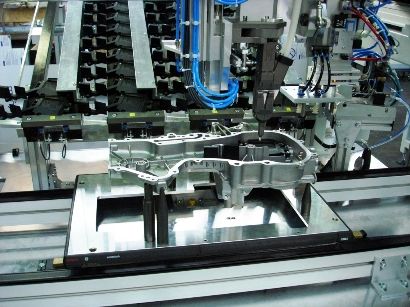 In the following assembly processes along the linear transfer system the individual components are assembled into the housing. They are monitored force-path. At the same time they are glued and oiled airtight. Special dosing systems leave this always the exact defined amount of the component. Other components are provided with electronic screwdrivers and various feeding systems. They screwing process is torque monitored.
Following the complete component is clamped in a specially designed hydraulic pressure test station, sealed and the individual chambers are tested for leaks.
Only now, after all components have been correctly, securely assembled and tested, the way is free for motor mounting.
EURO-line with coupled Assembly
 Overview
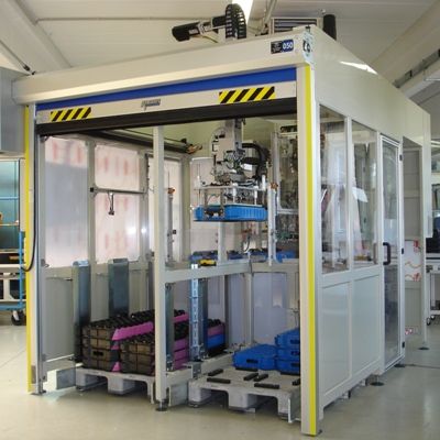
Combination of assembly and handling technology.
I this system motors are provided over trays from a palletiser. The engines are removed, set in a halfway house, and used after camera testing by the plug-in contacts in a valve block. The cycle time per composite unit is 12 sec.
 Palletizing/Depalletizing
The loading and transport of the system trays is done via euro-pallets. The loading and transport of the pallets from the palletizing cell is done manually, using trucks. 4 stacks of trays are located on the full range euro pallet. With a tray gripper system, the top tray from one of the stacks is removed and placed on a positioning table. The NC table axis moves the tray by the dozen under the YZ-axis combination from which the engines are taken out of the individual nests of trays.
 After unloading the tray, this is supported by the positioning table to the tray unloading side. The traygripper takes over the empty tray and puts down it on the empty pallet spaces.
Assembly station
The e-motor assembly is linear flanged-on at the palettiser cell.
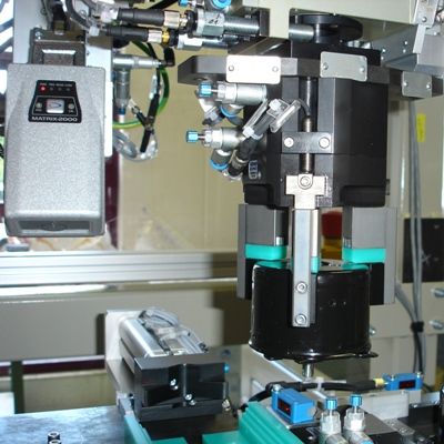
The motor which is taken with the palletiser handling out of the tray is detected in a detection position location accuracy plug contact by means of ultrasonic sensors. 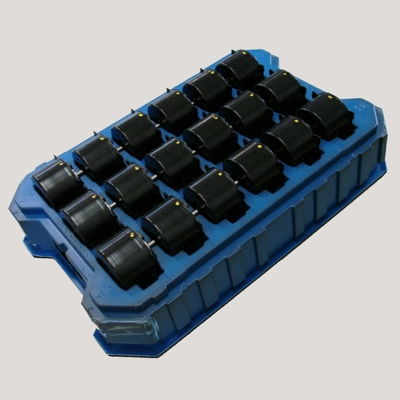 Then the motor with motor shaft is pushed down on a fixed direction unit.
There is a centring of the motor bearings and the motor housing.
With a joining / relayhandling, equipped with three-jaw gripper, X/Y measurement system and servo drive is the setting of the eccentric bearings motor shaft made.
After the closeing of the three-jaw gripper, the X / Y offset is determined direction from balancing head using the measuring system. In the S7 PLC software is the correction angle determined and approached by the servo motor. Thus, the motor shaft is aligned.
 Depending on the position detection of the plug contact the alignment of the motor shaft occurs 0 degrees or 180 degrees. If the position accuracy have been distorted by the plug contact for 180 degrees the motor is rotated at a certain NC Y axis with ist joining handling by 180 degrees. Before there is a motor shaft alignment.
The WT provided about the WT band system is stopped and dug through a Hub unit and fixed.
There is then a camera inspection of the ECU contacts on dimensional accuracy.
The manifold with pre-assembled piston and the needle bearing is centered in a mask. A pneumatic Y-Z handling with Swivel cylinder positioning the needle roller bearing on the inside wall of the valve block and tilts it back again to the theoretical clearance.
The forward-oriented engine is added by means of a servo Z axis on the valve block with directed and approved ECU plug.
Before the lifting unit releases the workpiece carrier to further a bar code query is carried out by means of a scanner.
Ultrasonic welding machine
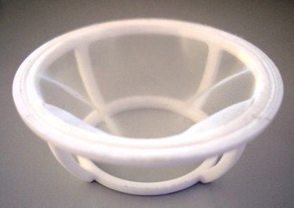
 The ultrasonic welding machine separates and welded Filterflies at the same time with a filter holder.
The system is designed as a semiautomatic and manufactured. An employee uses the filter-holder to be processed manually in the workpiece clamping.
A start button starts the joining process. After the welding process the finished part is released again the operator for manual removal.
Mounting system for telecommunications connector
 Assembly machine for plug housing (telecommunications)
The individual connectors are fed on the integration of a funding pot with appropriate feeding technology.
The contact strips are fed via a reel as endless belt of system. The punching and bending is carried out within the Assembly machines.
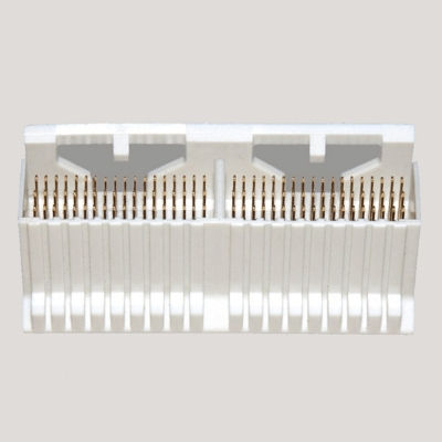 The housing are then optically measured. This is the angle/position and presence of the contacts with an accuracy of +/-5/100 mm measured. After the measurement, the connectors are labeled and packaged in blister. The cycle time of the plant is located at 15 sec. per connector with 72 individual contacts.